|
|
Post by sedguy77 on Jan 6, 2014 17:18:03 GMT -8
I have a couple early USD Calypsos (circa 1962-63) that I'm trying to bring back to usable condition. One came to me COMPLETELY disassembled, and the other has a working 1st stage (good solid IP of 120) but a leaking 2nd.
I was hoping to use the assembled one to guide my rebuild of the disassembled one, but since the 1st works well, I don't want to risk a problem by taking it apart to act as a guide.
That brings me to my question. In rebuilding the disassembled unit, I've run into a problem. I have several boxes of old USD parts from Aqua-Div, Hydrolung, Calypso I, III & IV, and Conshelf regs. In other words, I don't know what's what (yet). I got this mess of stuff from Ron Slonda. Unfortunately, the pins for all these regs are all together in a single box.
From diagrams, I can piece it all back together pretty much, but I have no idea of the pin length (Part 19 in the key: Part #1031-03) for a Calypso I.
I gather it is pointed, with a distinct head on it. A few of the supports in my box are mated with a pin that can't be removed. I assume those aren't it.
Any help would be great. Thanks!
|
|
|
|
Post by SeaRat on Jan 6, 2014 17:45:30 GMT -8
Item #19 in the diagram in Basic Scuba (Fred Robers' book) is Part number 1023-12, the Stem Gauge. There is a pin inside the stem gauge, and if that is the part you are thinking about, it is probably already there. You cannot see it until pressure is applied to the first stage.
John
|
|
|
|
Post by sedguy77 on Jan 6, 2014 18:30:17 GMT -8
Oh sorry, I'm referring to the diagram in the service manual (the one hosted on the VDH site; "Aqua-lung early manual.pdf" p. 44.) Specifically, this is the HP seat pin that is actuated by the diaphragm, i.e. the pin that is at the heart of all diaphragm regulators. If too short, it leaks; if too long, it gets bent, messes up the HP seat and possibly -- if REALLY too long -- gets stuck inside the guts of the reg.
Therefore, I've got to be absolutely certain to get it right. But you know all that, so why am I telling you this? Rather, let me just say it is Item #10 in the diagram in Basic Scuba (Fred Roberts' book, p. 184, 2nd ed.), Part 1023-16, "Pin".
I'm guessing almost no one actually knows that pin length off the top of their head (except maybe Greg Barlow? -- I know, if only it were a Voit) or has the specs, but hoped that maybe someone has a known spare sitting around that they could measure.
Thanks.
|
|
|
|
Post by nikeajax on Jan 6, 2014 19:11:08 GMT -8
Ahoy matey! You're talking about the actuator-pin, no? Ron is a REALLY good guy... VERY helpful... If'n you can wait till tomorrow, I will take mine out and measure it for you... 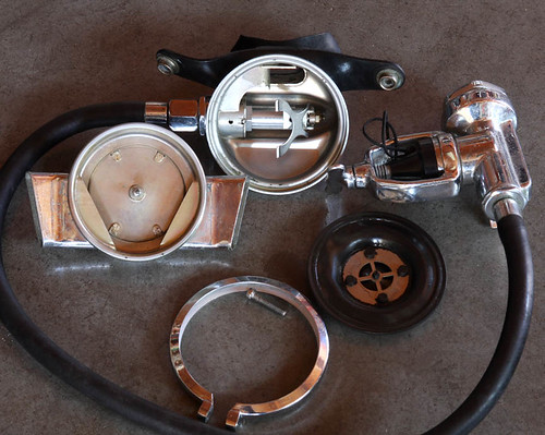 Jaybird |
|
|
|
Post by sedguy77 on Jan 6, 2014 19:44:31 GMT -8
Ahoy matey! You're talking about the actuator-pin, no? Ron is a REALLY good guy... VERY helpful... If'n you can wait till tomorrow, I will take mine out and measure it for you... Jaybird Jaybird: I was hoping I'd hear from you. I read your old posts about Calypso overhauls as well as many other subjects over the years. I've been a lurker for a LONG time. Likewise, I have gained a LOT of useful info from Ron via his prolific and very helpful posts. I suspect I will end up needing some additional help when it comes the 2nd stage of both of these regs. I find USD 2nd stages cumbersome at best when tweaking WOB. Especially the early ones. Unfortunately, one of these is so early that it has the all metal body (even the exhaust), and the proprietary hose fitting (i.e. the end "cap" is part of the reg and crimped to the hose -- they cannot be separated). Fortunately, the hose and diaphragm seem to be in workable condition. Only the LP soft seat is perished (I hope!) In any case (I digress ...) I really appreciate the offer of the measurement. To date in my reg rebuild history, I have managed to avoid using the wrong pin length. I would hate to start with this little beauty. The chrome is gorgeous and I would hate to have to scrounge parts at this stage of the game. Thanks. |
|
|
|
Post by sedguy77 on Jan 6, 2014 19:47:48 GMT -8
Oops! Again, I'm telling people things they obviously already know. That photo is the spittin' image of my assembled reg. Right down to the "double diaphragm" and the proprietary hose fitting. And thanks for that photo by the way -- now I can confirm my suspicions about which of my yoke screws is original.
|
|
|
|
Post by nikeajax on Jan 7, 2014 10:16:25 GMT -8
The length I got is 5/8", and yes, it looks like a finishing-nail; it has a head on one end... More later...
Jaybird
|
|
|
|
Post by sedguy77 on Jan 7, 2014 13:26:31 GMT -8
Many, many thanks. "finishing nail" - now why didn't I think of that? Great description. That means I'm on my way on the 1st stage.
As I mentioned, I figured the 2nd would give me trouble and it has. In this case, I'm going to reference Roberts' "Basic Scuba" for my parts description. I removed the cover (#49) only AFTER trying to remove the inlet valve nipple (#31). I gather that was a mistake. What I discovered was that the IVN rotated but did not budge. Rather what I was doing was unscrewing the valve "body" (# 37; part # 1025-09) from the bottom box. Fortunately, I don't seem to have done any damage with this ham-fisted move. Now I have the interior more-or-less disassembled to reveal a badly scored soft seat -- the source of my free flow.
But this raises several interesting and important questions (in my mind at least) ... why the heck does the IVN (#31) NOT screw out? Roberts' diagram makes it seem likely. Instead, it appears that (by design) it rotates in place within the bottom box inlet. And that isn't all; along with the nipple Roberts shows two o-rings: 32 & 28, which appear to belong upstream of the body key washer (#36; part no. 1025-16). My reg does not have these! Besides, why are there two o-rings that appear to be side by side (nested?)? Finally, what keeps water from intruding AROUND the nipple (since it appears to NOT be threaded into the bottom box) and into the interior of the 2nd stage, making for a leaky 2nd?
I figure I can replace the LP seat, put this back together like I found it, and adjust the lever for an acceptable cracking effort. But now I'm confused as to why this doesn't appear to have water tight components as illustrated in Roberts. I'm a little baffled and afraid this is going to end up as a wall-hanger if I don't somehow get better informed. I don't have a service manual that goes this far back, so I'm kind of in the dark.
|
|
|
|
Post by nikeajax on Jan 7, 2014 13:26:37 GMT -8
Adjusting the second stage is really easy as compared to any of the later models. Use a paper-clip to hold the poppet, keep it from rotating while you adjust the lock-nut. In my image, you can see two holes, one is partially covered up by the lever: the poppet has a hole in its shaft too: it's called a disc and retainer in the manual and book, but it's still a poppet! You may be able to just flip the LP-seat, but if it's already flipped, you can make your own LP-seat with a paper-punch, and the proper thickness of neoprene. The exhaust valve is a 22-23mm, this is not critical, as either one will work! Get a new silicone one at any dive shop, just tell them it's for a snorkel, other wise they may accuse you of being "51-50" (a danger to yourself and others) if they sell you that part...  Jaybird |
|
|
|
Post by SeaRat on Jan 7, 2014 13:33:52 GMT -8
The Scubapro Son-of-a-Gun snorkel from the 1980s has a silicon non-return which works perfectly in this diaphragm.
John
|
|
|
|
Post by nikeajax on Jan 7, 2014 15:34:31 GMT -8
Okay, what'cha wanna do is ge'cher self-a 9/16" open-end wrench to hold the body (#37, or Part No.1025-09)while turning inlet-valve-nipple with a, what is that a 3/4" wrench? You kinda wanna put pressure on the 9/16" wrench toward the INV, while also applying pressure, with your finger, to the body (#37). You'll want to do the same thing while reassembling it. The INV will come off--just be patient with yourself: if you find yourself turning into this guy:  Walk away, cool off... WARNING!!!!!Reassemble slowly and deliberately!!!!! It's super easy to (expletive-deleted)-up your lever; ask me how I know! No. 36 (1025-16) is keyed and can be kind tricky to keep from walking around while reassembling: this is why you need to keep that pressure on it... Jaybird |
|
|
|
Post by nikeajax on Jan 7, 2014 16:52:43 GMT -8
Okay Sedguy, can we get a better moniker? I just like talking, or writing, to someone who has a name, jeez, just make one up if'n you'd rather not say!  Yeah, that dingus is a joke, the hose, as you called it, "proprietary", is a bunch'o ca-ca! What I did was get a C-II, as they have same first stage, but you can use a different hose, and put it on my C-I. I used a hose-T to ad an octo, and used the C-II second stage as the octo. The C-II second stage is totally different than the C-I, as you know, but they still kept the 22mm exhaust diaphragm! The exhaust-T on the C-II is VERY restrictive, which is why it doesn't breath as well as the C-I. With the C-II first stage, I have a doner, or parts reg I've been thinking of doing a comparison of the Calypsos I & II with the Sportsways Navy Units: their exhaust diaphragm is the same but has a more robust "T" than the C-II, and is like a much more modern exhaust-T. I think the Sportsways and the C-I should be very much comparable, as I've never heard anyone say ANYTHING bad about either of their breathing characteristics... Jaybird |
|
|
|
Post by SeaRat on Jan 7, 2014 17:15:30 GMT -8
Jaybird, on March 14, 2013 I conducted some regulator resistance studies using a Dyer Mk II, Model 25 Inclined Plane Monometer, calibrated to zero inches of water, and balanced to level. I had these regulators in water (my face was not), so there was a bit of water pressure on them (probably about 1/2 inch). The Calypso III was approved for U.S. Navy use, but I don't think the Navy EDU approved the original Calypso or the Calypso II. However, we did use both in the U.S. Air Force Pararescue. This is also a regulator that William H. Pitsenbarger was photographed using as a USAF Pararescueman; he won the Medal of Honor for his actions in Vietnam, which he did not survive. This regulator was also used by Hannes Keller on his record-breaking deep dives, using mixed gas that at that time was secret.   John |
|
|
|
Post by nikeajax on Jan 7, 2014 18:01:06 GMT -8
John, just curious, what was your IP for each of those regs? I know for the C-I&II they suggested 120-psi, but as I recall they bumped it up to 135-psi on later models. I set all of my single hoses at 135; or rather will, I need to get the shims for my Healthways...
Jaybird
|
|
|
|
Post by sedguy77 on Jan 7, 2014 21:35:11 GMT -8
Jaybird,
Sedguy IS my name; folks just call me Guy (last name) -- works out well.
As far as the removal goes, I don't think I made myself clear. I already removed the valve body (#37, or Part No.1025-09 with 9/16" fitting); it wasn't easy, but it's out without incident. The inlet valve nipple, on the other hand, just turned without screwing out. It is (?)permanently fixed in the bottom box. Roberts' illustration suggests otherwise, but no matter how many times I turn that 7/8" fitting, all it does is rotate in place. I suspect I could knock it out of there, but since I might damage the bottom box or the orifice, I'll likely not even try.
But even more importantly, how about those o-rings that I seem to be missing? I thought it over, and that could (and probably does) explain the 2nd stage leak, rather than (or in addition to) a bad LP seat. So what I really need is confirmation of their presence in your original C-I first stage, and their sizes. I could do it by trial and error, but what with the IVN not wanting to come out, I'd rather not. So let me repeat: TWO (MISSING) O-RING SIZES and PLACMENT? (Parts 32 & 28; 8201-14 & 8200-16, respectively; I figure this post is so long, I should emphasize my needs.) I'm guessing that means a -114 and a -016 o-ring size, but neither have obvious seating surfaces within the IVN or the bottom box. So my next guess is that they go within the bottom box inlet before the IVN is inserted. If so, that REALLY complicated my situation.
It is worth noting, that the IVN isn't the only removable part in this reg that can't (easily) be removed. Somebody took a punch (or the like) and pinned the pin guide (Part #9; 1023-15) into the first stage. They REALLY wacked that sucker. Cannot be remove now no matter what! This isn't the first of those I've seen in C-I first stages either. I know of a tech who tried to remove one a couple decades ago, and it destroyed the 1st stage body. But I digress. My guess is that the IVN has stripped its outer threads (if it ever had any). The IVN internal threads have been fenestrated (drilled through w/multiple "windows") and I see no evidence of threads that way. But I can say that the IVN is in there TIGHT. It will not budge without gettin' wacked.
As far as the LP seat goes, I've got a couple dozen to choose from, so no sweat. The original one has not been flipped, but the back side has a very irregular surface so I'm tossing it. I've seen a few of these as well -- almost look wrinkled! My hope is to stick with the C-I 2nd stage. I have a couple C-II's and as you say, the restricted exhaust ports make for a poor breather. But more to the point, I dig the vintage, all metal look of the C-I 2nd. One way or another, I want to get it up and running again.
Finally, thanks to you both for the exhaust valve advice. The original is a bit soft (even after hours of FG silicone) and has taken a significant a set from the purge. I imagine a silicone version might give lower exhalation effort as well. Plus I have an out-of-commission snorkel that needs a new one of that size as well! Hopefully, this will convince a LDS to provide me with a replacement or two.
Guy
|
|