|
|
Post by SeaRat on Feb 26, 2014 18:12:55 GMT -8
Just make sure your gauge has a bleed valve.
John
|
|
|
|
Post by SeaRat on Feb 27, 2014 15:55:23 GMT -8
I have just in the past two days compared the older and the newer Dacor Double Diaphragm exhalation diaphragms. What I found was shocking. Before I get into that, let me refer to a quote from the U.S. Navy Experimental Diving Unit in their first report (NEDU_1960_09eval.pdf) on the Dacor Dial-A-Breath regulator: With this in mind, I took one of their older diaphragms and one of their newer diaphragms for exhalation on the Dial-A-Breath (original and R-4) and compared their cross-sectional area. Original Diaphragm: Six circular openings behind the mushroom valve, 7 mm in diameter (3.5 mm in radius). Area = pi x radius squared = 3.1416 x 3.5squared = 38.5 mm squared Total area = 38.5 mm squared x 6 = 230.0 mm squared R-4 Low Modulus Diaphragm There are three rectangular openings behind the mushroom valve. These measured 7 x 10 mm = 70 mm squared 70 mm squared 70 mm squared x 3 = 210 mm squared Note that the newer, low modulus diaphragm has less area than the older diaphragm. I'm wondering what the designers were thinking when they put this together will less surface area than the original? John  Attachments:
|
|
|
|
Post by nikeajax on Feb 27, 2014 16:38:11 GMT -8
Gosh, I wonder if it was the same dope that was responsible for this: 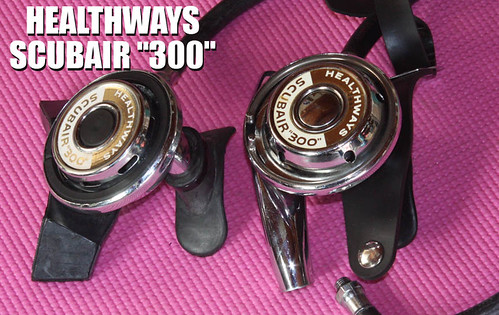 The one on the left, "Gosh, it looks new anyway..." Jaybird |
|
|
|
Post by nikeajax on Mar 18, 2014 17:44:43 GMT -8
John, I was looking at that bottom can you sent me: I didn't realize that Dacor used two different styles of second stage valve bodies  I can see safety-glasses and hearing protection will be needed in my adjusting the IP: I really hate loud noises and I anticipate very loud noises when I pull the IP gauge out of that hole. Can you say trepidation? Jaybird |
|
|
|
Post by nikeajax on May 21, 2014 9:57:00 GMT -8
I'm getting ever closer Dave!
Okay, I finally got it! 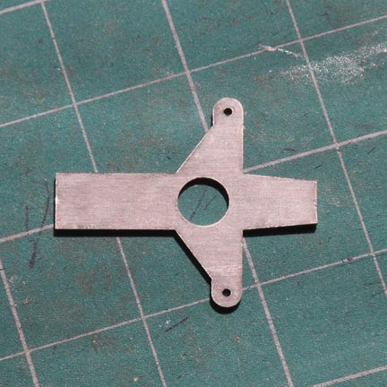 Now I have to do some bending and put a dimple in the longer tang/lever. Jaybird
|
|
|
|
Post by nikeajax on May 21, 2014 12:18:06 GMT -8
I'm almost there, but that rear tang/lever is taking a lot of fine tuning: it has to come back about 1/16" before I put the bend in!
Jaybird
|
|
|
|
Post by SeaRat on May 21, 2014 12:53:42 GMT -8
Jaybird, be careful about the interstage pressure when you get things assembled. I have never tried to take the interstage pressure on my Dacor double hose regulators, but rather used the adjusting nut to set the pressure until it slightly leaks, then back it off a bit. The original Dial-a-Breath doesn't have that option, but the R-4/Clipper does (to adjust the interstage pressure). If your gauge doesn't have a means of holding it down, don't use it, as the pressure can be more than a person can normally hold down.
John
|
|
|
|
Post by nikeajax on May 21, 2014 13:24:03 GMT -8
John, thanks for the heads up: I plan on making a special screw-in adapter for setting the IP. Yeah, I thought about doing it the way they suggest in the Dacor-manual, and, well, it kinda scares the ca-ca outta me  If it works, I'll let you borrow it, just so you can be official  Jaybird |
|
|
|
Post by nikeajax on May 21, 2014 13:41:32 GMT -8
YAHOOOOOO!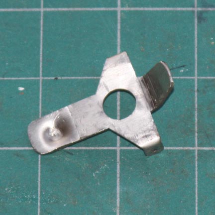 Jaybird
|
|
|
|
Post by sitkadiver on May 21, 2014 17:12:07 GMT -8
the rearlever looks like more than 35 degrees.... Did you fit in place and find you needed to change the original design?
It looks awesome.
|
|
|
|
Post by nikeajax on May 22, 2014 9:26:56 GMT -8
Dave, I ended up just eyeballing it in the end, but yeah, I think it's somewhere between 40-45 degrees. My original design doesn't allow it to rest on the poppet correctly, so I had to bring the tang back further before I beginning the bend...
Jaybird
|
|
|
|
Post by nikeajax on May 22, 2014 11:08:08 GMT -8
John, how robust is the spring giving this lever tension? I don't have one and I need to figure that out...
Jaybird
|
|
|
|
Post by nikeajax on May 23, 2014 14:08:48 GMT -8
Can anyone give me the specs on the spring that tensions the levers: height and wire-gauge of the spring? Don't make me grovel  jaybird |
|
|
|
Post by SeaRat on May 24, 2014 17:12:16 GMT -8
Jaybird, I don't know the specs on that LP spring. I have one, but the only way to figure it out is to take my R-4/Clipper (I put the R-4 second diaphragm on it) apart and look. There is a way of calculating this value too. You have to know about lever systems, the force on the seat (psig x seat area in inches) to get the number needed for the spring. It is not a really heavy spring either, as the leverage is pretty good against the seat. Let me think about it, and I might be able to calculate this number.
John
|
|
|
|
Post by SeaRat on May 24, 2014 17:58:14 GMT -8
Okay gang, this is what I got, and taking to my machinist: 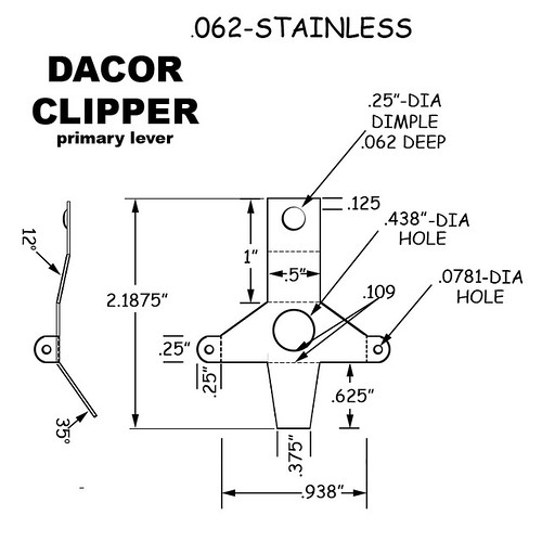 Jaybird Okay Jaybird, Here's how I'd go about the calculation: The force needed in pounds to close the seat would be equal to the force on the other side of the seat divided by the leverage of the primary lever. The secondary lever has nothing to do with this seat closure. We'll use an interstage pressure of 140 psig. So let's look at the math. We'll assume that the diameter of the hole is 0.25 inches. Area is equal to pi times the radius squared. A = pi x r 2 = 3.1416 x (0.25/2 inches) 2 = 0.0498 square inches Force = pressure (in lbs/in 2) x area (square inches) = 140 lbs/ in2 x 0.0498 in2 = 6.87 lbs = 7 lbs According to your diagram above, the fulcrum of this lever to the end of the lever which sits on the seat is 0.75 inches, but the point is somewhat in front of this where the valve seat hits the lever, so we'll say it is 0.70 inches. The overall length of the lever is 2.1875 inches, and the dimple where the spring would push is 0.125 inches from the end, and is 0.25 inches in diameter. So this would make the center of the lever on the spring end 0.25 inches from the end (0.125 + (0.25/2) = 0.25 inches). To get the length of the lever arm from the fulcrum to the spring, we can use the total length of 2.1875 inches, subtract 0.25 inches from that (for the dimple) and get 1.9375 inches total from the spring center to the place where the seat impinges on the lever on the other end. Subtract the 0.7 inches from the fulcrum to the seat, and we get 1.2375 inches. So the leverage is the length of the spring end divided by the length of the seat end of the lever system. That would be: Leverage = spring end length / seat end length = 1.2375 inches / 0.7 inches = 1.77 The spring strength needed is therefore: 6.87 lbs / 1.77 = 3.88 lbs = 4 lbs So you need a spring that can exert at least 4 lbs of force against the lever. If I were you, I'd go a bit higher, and get a spring that at the compression you use for the regulator would give you about 5-6 pounds of force. Be sure that this is a stainless steel spring, and that it has enough compressibility to give that force at the height of the lever you are using. Note that I did not make any adjustments for the angle of the levers. My understanding is that this is not necessary, as the force around the fulcrum is in a circular motion, and the angle should not matter. But also realize that I'm not an engineer, but have some training in basic force mechanics from the safety and health field, which is what I'm applying here. So if any of you engineers out there want to check my figures, please feel free to do so. Also, because I am not an engineer, I can only say that these are my calculations, and should work but I cannot state unequivocally that they will. Only a bit of experimentation will do that. Also note that I assumed that the chamber diameter was 0.25 inches, and it may be larger. If it is, re-do these calculations using the correct number and it should give you an answer you can use. John |
|


 I can see safety-glasses and hearing protection will be needed in my adjusting the IP: I really hate loud noises and I anticipate very loud noises when I pull the IP gauge out of that hole. Can you say trepidation?
 If it works, I'll let you borrow it, just so you can be official